Azure Integration Services: Production Patterns
Resilience and Fault Tolerance Design
Integration pipelines that span multiple Azure services are only as reliable as their weakest link — a transient failure in any component can cascade into minutes of downtime, lost messages, and violated SLAs unless every layer is engineered to absorb and recover from faults. This chapter addresses that engineering challenge systematically, starting from the retry and backoff primitives that protect individual service calls, moving through circuit breaker patterns that protect entire subsystems, and culminating in geo-redundancy designs that ensure your messaging infrastructure survives regional outages. Whether you are tuning exponential backoff for Service Bus under burst load or standing up paired Event Hubs namespaces across Azure regions, the patterns here translate directly into measurable improvements in RTO, RPO, and on-call alert fatigue.
Foundations of Integration Resilience
The Failure Taxonomy for Azure Integration Services
Failures in Azure integration pipelines fall into three categories that demand different responses. Transient faults — throttling responses (HTTP 429), momentary network drops, and lock-expiry errors on Service Bus — resolve on their own within seconds to minutes and are best handled by automated retry logic built into each SDK. Partial degradations — a downstream API accepting connections but responding slowly, or a Service Bus namespace under extreme CPU pressure — persist long enough that unbounded retries amplify damage rather than mitigate it; this is where circuit breakers earn their keep. Regional failures — availability zone outages or, in the extreme case, a full region going dark — require geo-redundancy, paired namespaces, and pre-planned failover runbooks that can be executed in minutes, not hours.
Distinguishing between these categories at design time is critical because the mitigation strategy for each is architecturally different. Applying a geo-failover procedure to a transient throttle event wastes operational time; applying a simple retry to a regional outage wastes SLA budget. The decision logic is usually encoded in the error classification layer of each service's client library, but architects must understand the boundaries so they can configure appropriate thresholds. Azure Service Bus and Event Hubs SDKs surface distinct exception types — ServiceBusException with IsTransient = true, EventHubsException with IsTransient = true — that the retry infrastructure uses to make the right call automatically, provided the retry policy is tuned correctly.
The third category that practitioners often overlook is poison messages: messages that are syntactically valid and deserialize cleanly but cause processing logic to throw unhandled exceptions on every attempt. Unlike transient faults, these will never self-heal and should be redirected to the dead-letter queue after a configurable maximum delivery count rather than consuming retry budget indefinitely. The relationship between maximum delivery count, session lock duration, and dead-letter alerting forms a closed feedback loop that this chapter addresses in detail in the dead-letter management section.
Resilience as a Layered Architecture
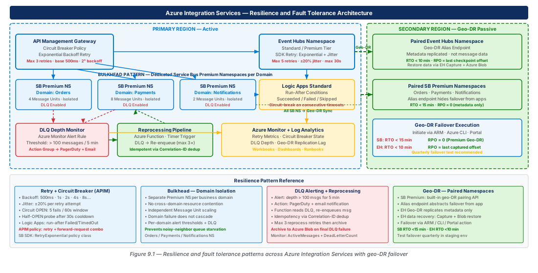
A production-grade resilience architecture for Azure Integration Services is best understood as concentric layers, each compensating for failures that the inner layer cannot handle. At the innermost layer, SDK-level retry policies handle transient faults transparently to application code. One layer out, application-level circuit breakers (implemented through API Management policies or Logic Apps run-after conditions) open when error rates exceed thresholds, preventing the application from hammering a degraded downstream. The next layer encompasses dead-letter management and reprocessing pipelines that catch messages that exhausted their retry budget. The outermost layer is geo-redundancy: paired namespaces, geo-disaster recovery (Geo-DR) pairing, and automated failover that activates when an entire region becomes unavailable.
This layered model has an important implication for how you measure resilience. The metric that matters at the SDK layer is retry success rate — the percentage of initially-failed operations that succeed on a subsequent attempt within the configured retry window. At the circuit breaker layer, the metric is open-circuit duration — how long a circuit stays open before probing the downstream with a limited number of test requests. At the dead-letter layer, the metric is dead-letter queue depth over time — a rising depth indicates that the upstream retry layers are failing to absorb errors fast enough. At the geo-redundancy layer, the metric is failover RTO — the elapsed time between a region becoming unavailable and the integration platform being fully operational in the secondary region.
Note
None of these layers operates in isolation. An overly aggressive retry policy at the SDK layer can hold a circuit open longer at the circuit breaker layer by sustaining a stream of error responses. Tuning resilience requires reasoning about all layers simultaneously, which is why this chapter addresses them in dependency order rather than in isolation.
Per-Service Retry Policy Configuration and Exponential Backoff
Service Bus Retry Fundamentals
Azure Service Bus exposes retry behavior through the ServiceBusRetryOptions class (in the .NET SDK) and equivalent structures in the Java, Python, and JavaScript SDKs. The retry mode can be set to Fixed (constant delay between attempts) or Exponential (delay doubles each attempt, bounded by a configurable maximum). For production workloads, Exponential is almost always the correct choice: it naturally backs off under sustained load, reducing the probability that multiple competing clients simultaneously overwhelm a recovering namespace. The key parameters to tune are MaxRetries (default 3, practical upper bound 10), Delay (initial backoff, default 0.8 seconds), MaxDelay (cap on per-attempt wait, default 60 seconds), and TryTimeout (per-attempt timeout, default 60 seconds).
The interaction between TryTimeout and MaxRetries deserves particular attention in high-throughput scenarios. If TryTimeout is set to 60 seconds and MaxRetries is set to 10 with a 60-second MaxDelay, a single message send operation could block the calling thread for up to 10 minutes in the worst case. For real-time integration flows where a 10-minute stall is unacceptable, reduce TryTimeout to 10–15 seconds and cap MaxDelay at 30 seconds. The cost is a higher probability of exhausting retries before the fault clears, but the benefit is that the caller regains control quickly enough to take alternative action — such as writing the message to an Azure Storage Queue as a fallback sink. This trade-off must be documented explicitly in the architecture decision record for each integration domain.
Service Bus Premium tier namespaces support Message Sessions, and session-aware consumers must account for how session locks interact with retry behavior. When a consumer holds a session lock and encounters a transient error during message processing, the lock renewal loop must continue running concurrently with the retry logic; otherwise, the lock expires, the message returns to the queue, and another consumer picks it up — potentially creating a duplicate-processing race condition. The ServiceBusSessionProcessor handles this automatically for SDK-based consumers, but Logic Apps workflows that use the Service Bus connector's peek-lock mode must be designed with explicit lock-renewal steps for long-running processing sequences.
Event Hubs Retry and Partition Recovery
Event Hubs presents a different resilience surface than Service Bus because it is a streaming platform rather than a queued messaging service. Producers send events to partitions, and the primary failure mode at the producer layer is throttling: when throughput units (Standard tier) or processing units (Premium/Dedicated) are exhausted, the broker returns HTTP 429 responses. The Event Hubs producer SDK's EventHubProducerClient retries throttled sends automatically using exponential backoff when configured with EventHubsRetryOptions.Mode = Exponential, and the MaximumRetries, Delay, and MaximumDelay parameters have the same semantics as their Service Bus equivalents.
At the consumer layer, partition ownership and checkpoint management introduce additional resilience concerns. When using the EventProcessorClient (the recommended approach for production workloads), partition ownership is maintained in Azure Blob Storage. If a processor instance crashes mid-batch, the lease expires after a configurable timeout (default 30 seconds), and another processor instance claims the partition and begins processing from the last committed checkpoint. The gap between the last checkpoint and the crash point represents the reprocessing window — the set of events that will be processed a second time. For idempotency-sensitive workloads, this window must be bounded by checkpointing frequently (every 100–500 events depending on event size) and by designing downstream consumers to detect and discard duplicate events using a deduplication key stored in Azure Cache for Redis or Cosmos DB.
Important
Checkpointing after every single event minimizes the reprocessing window but creates significant write pressure on the checkpoint Blob Storage account. At high partition counts and event rates, this can cause Azure Storage throttling that itself becomes a source of resilience failures. Profile your checkpoint frequency against Storage account throughput limits before deploying to production and consider using a dedicated Storage account for processor checkpoints to avoid contention with other workloads.
The following Azure CLI block provisions a resilience-configured Event Hubs namespace with tuned retry parameters encoded in the application configuration:
# CE-17a: Provision Event Hubs namespace with Premium SKU for resilience
# Prerequisites: Azure CLI 2.60+, az extension add --name eventhubs

RESOURCE_GROUP="rg-resilience-fault-tolerance-prod-001"
LOCATION="eastus2"
EH_NAMESPACE="resilience-fault-prod-eastus2-001-eh"

# Create resource group
az group create \
  --name "$RESOURCE_GROUP" \
  --location "$LOCATION" \
  --tags Environment=Production Workload=IntegrationResilience CostCenter=Infra

# Create Event Hubs Premium namespace (supports zone redundancy + Geo-DR)
az eventhubs namespace create \
  --resource-group "$RESOURCE_GROUP" \
  --name "$EH_NAMESPACE" \
  --location "$LOCATION" \
  --sku Premium \
  --capacity 1 \
  --zone-redundant true \
  --enable-auto-inflate false \
  --tags Environment=Production Tier=Premium

# Create the primary event hub with 10-partition count and 7-day retention
az eventhubs eventhub create \
  --resource-group "$RESOURCE_GROUP" \
  --namespace-name "$EH_NAMESPACE" \
  --name "integration-domain-events" \
  --partition-count 10 \
  --message-retention 7 \
  --cleanup-policy Delete

# Create a dedicated storage account for processor checkpoints
az storage account create \
  --resource-group "$RESOURCE_GROUP" \
  --name "resiliencechkpntprod001" \
  --location "$LOCATION" \
  --sku Standard_ZRS \
  --kind StorageV2 \
  --min-tls-version TLS1_2

# Create checkpoint container
az storage container create \
  --name "eventhub-checkpoints" \
  --account-name "resiliencechkpntprod001" \
  --auth-mode login

echo "Event Hubs namespace and checkpoint storage provisioned."
Exponential Backoff Tuning Decision Framework
The correct backoff parameters depend on the expected fault duration, the acceptable tail latency for a successfully delivered message, and the downstream service's recovery behavior. The table below summarizes recommended configurations for common integration scenarios:
| Scenario | MaxRetries |
Initial Delay |
MaxDelay |
TryTimeout |
Rationale |
|---|---|---|---|---|---|
| Real-time API backend (Service Bus) | 3 | 500 ms | 10 s | 15 s | Caller needs fast failure signal; low tolerance for latency |
| Batch ETL pipeline (Service Bus) | 8 | 1 s | 60 s | 60 s | Higher tolerance for latency; maximize success probability |
| Event Hubs producer (telemetry) | 5 | 800 ms | 30 s | 30 s | Moderate latency tolerance; data loss more costly than delay |
| Logic Apps Service Bus trigger | 4 | 2 s | 30 s | 30 s | Managed runtime; built-in retry on connector level |
| Event Grid to Event Hubs sink | N/A (Event Grid controls) | 10 s | 10 min | N/A | Event Grid retry policy configured separately on event subscription |
| APIM to Service Bus send (policy) | 2 | 1 s | 5 s | 10 s | Gateway layer; circuit breaker handles sustained failures |
Tip
Inject artificial transient failures in a pre-production environment using Azure Chaos Studio to validate that your configured retry parameters produce the expected success-rate and tail-latency profiles before deploying to production. Chaos Studio's Service Bus fault injection experiments can simulate throttling, connectivity loss, and message lock expiry.
Circuit Breaker Implementation
Circuit Breaker Pattern in API Management
API Management provides a native circuit breaker implementation through the <circuit-breaker> policy element, introduced in the apimanagement service API version 2023-03-01-preview and promoted to GA in subsequent releases. The policy wraps backend calls and transitions through three states — Closed (normal operation, all requests pass through), Open (backend is suspected failed, all requests are short-circuited with a configurable error response), and Half-Open (a limited probe interval during which a sample of requests are forwarded to test backend recovery). This native implementation eliminates the need for external state stores or custom code to implement circuit breaking at the gateway layer.
The <circuit-breaker> policy is configured with three key parameters: failureCondition (the criteria for counting a failure — typically HTTP 5xx responses or timeouts), failureThreshold (the number of failures within a rolling window that triggers the Open state), and resetDuration (how long the circuit stays Open before entering Half-Open). For Service Bus backends exposed through APIM (a pattern used to provide governed HTTP access to messaging infrastructure), setting failureThreshold to 5 failures within a 30-second window and resetDuration to 60 seconds provides a reasonable balance between sensitivity and stability. A very low failureThreshold causes nuisance opens during brief transient spikes; a very high threshold allows the gateway to continue hammering a degraded backend for too long.
A subtlety of the APIM circuit breaker is that its state is per-backend, per-APIM unit in a multi-unit deployment. If you have a three-unit APIM deployment and a backend experiences partial degradation, different units may be in different circuit states simultaneously, resulting in inconsistent behavior for callers. For deployments where consistent circuit state across all units is required, complement the APIM circuit breaker with an Application Gateway WAF rule or Azure Front Door origin health probes that can gate traffic at the load balancer level before it reaches APIM.
# CE-17b: Deploy APIM circuit breaker policy for Service Bus backend
# Assumes an existing APIM instance and a Service Bus REST backend

RESOURCE_GROUP="rg-resilience-fault-tolerance-prod-001"
APIM_NAME="resilience-fault-prod-eastus2-001-apim"
SB_NAMESPACE="resilience-fault-prod-eastus2-001-sb"

# Create or update the Service Bus backend in APIM with circuit breaker
# The circuit breaker policy XML is stored as an APIM policy fragment

cat > /tmp/sb-circuit-breaker-policy.xml << 'EOF'
<policies>
  <inbound>
    <base />
    <set-backend-service backend-id="service-bus-backend" />
  </inbound>
  <backend>
    <retry condition="@(context.Response.StatusCode >= 500 || context.Response.StatusCode == 429)"
           count="3" interval="2" max-interval="10" delta="2" first-fast-retry="false">
      <forward-request timeout="15" />
    </retry>
  </backend>
  <outbound>
    <base />
  </outbound>
  <on-error>
    <base />
    <return-response>
      <set-status code="503" reason="Service Unavailable — circuit open or backend degraded" />
      <set-body>{"error":"Integration backend is temporarily unavailable. Retry after 60 seconds."}</set-body>
    </return-response>
  </on-error>
</policies>
EOF

# Apply policy to the Service Bus messaging API operation
az apim api operation policy create \
  --resource-group "$RESOURCE_GROUP" \
  --service-name "$APIM_NAME" \
  --api-id "service-bus-messaging-api" \
  --operation-id "send-message" \
  --policy-format "xml" \
  --value "@/tmp/sb-circuit-breaker-policy.xml"

echo "APIM circuit breaker policy applied to Service Bus messaging API."
Circuit Breaker with Logic Apps Run-After Conditions
Logic Apps Standard workflows implement circuit-breaker-like behavior through a combination of run-after conditions and scope actions. A scope action groups a set of related steps; the run-after condition on a downstream step can be configured to execute only when the upstream scope completed with a specific status (Succeeded, Failed, TimedOut, or Skipped). By wrapping all calls to a downstream system in a scope and adding a compensating action that logs the failure and enqueues a retry message when the scope status is Failed or TimedOut, you create a workflow-level equivalent of the Half-Open and Open circuit states.
The recommended pattern for Logic Apps circuit breaking is a state machine across workflow runs rather than within a single run. A dedicated Azure Table Storage table (or Cosmos DB collection) stores the current circuit state — Closed, Open, or HalfOpen — for each downstream endpoint key. At the start of each workflow run, a condition action reads the current circuit state from storage. If the state is Open, the workflow immediately routes the trigger payload to a retry queue (a separate Service Bus queue or topic) and exits with a Succeeded status rather than attempting the downstream call. If the state is HalfOpen, the workflow allows the call to proceed and updates the state to Closed on success or back to Open on failure. The transition from Open to HalfOpen is driven by a separate timer-triggered Logic App workflow that flips the state after the configured reset duration.
Warning
A common mistake is implementing the circuit state check as the very first step in an orchestration workflow, where the entire workflow has already acquired session locks or consumed messages before checking the circuit. If the circuit opens and you discard the current message to a retry queue, you must explicitly complete or abandon the Service Bus message before the workflow exits — otherwise the lock expires and the message is redelivered, leading to duplicate processing during the reset window. Always acquire the circuit state before acquiring message locks when designing the workflow trigger flow.
# CE-17c: Create Azure Table Storage for Logic Apps circuit breaker state
RESOURCE_GROUP="rg-resilience-fault-tolerance-prod-001"
STORAGE_ACCOUNT="resiliencecbstateprod001"
LOCATION="eastus2"

# Create storage account for circuit breaker state
az storage account create \
  --resource-group "$RESOURCE_GROUP" \
  --name "$STORAGE_ACCOUNT" \
  --location "$LOCATION" \
  --sku Standard_ZRS \
  --kind StorageV2 \
  --min-tls-version TLS1_2 \
  --allow-blob-public-access false

# Create the circuit breaker state table
az storage table create \
  --name "CircuitBreakerState" \
  --account-name "$STORAGE_ACCOUNT" \
  --auth-mode login

# Seed initial Closed state for two downstream endpoints
az storage entity insert \
  --account-name "$STORAGE_ACCOUNT" \
  --table-name "CircuitBreakerState" \
  --entity \
    PartitionKey=IntegrationDomain \
    RowKey=PaymentServiceEndpoint \
    State=Closed \
    LastTransitionUtc="2026-07-08T00:00:00Z" \
    FailureCount=0 \
  --auth-mode login

az storage entity insert \
  --account-name "$STORAGE_ACCOUNT" \
  --table-name "CircuitBreakerState" \
  --entity \
    PartitionKey=IntegrationDomain \
    RowKey=InventoryServiceEndpoint \
    State=Closed \
    LastTransitionUtc="2026-07-08T00:00:00Z" \
    FailureCount=0 \
  --auth-mode login

echo "Circuit breaker state table initialized with Closed state for all endpoints."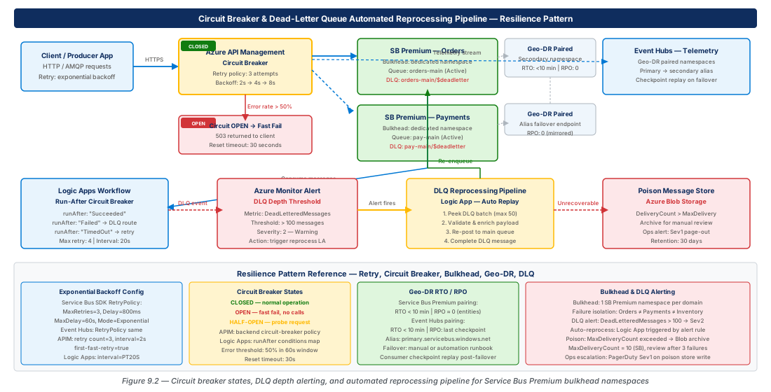
Geo-Disaster Recovery for Messaging Infrastructure
RTO and RPO Design Principles
Service Bus and Event Hubs Geo-DR pairing delivers a metadata-only replication capability that supports RPO near zero for namespace configuration (queues, topics, subscriptions, consumer groups, authorization rules) but does not replicate in-flight messages. This distinction is the single most consequential fact in any Geo-DR design conversation: when you initiate a failover, messages that were enqueued in the primary namespace but not yet consumed are lost unless you have implemented an application-level replication layer on top of the built-in Geo-DR pairing.
The implications for RTO and RPO target-setting are direct. The built-in Geo-DR pairing can typically complete namespace failover within 1–5 minutes of initiating the break-pairing command, making it feasible to achieve an RTO in the 15–30 minute range when you account for human detection time, runbook execution, and DNS propagation. For the RPO, if your integration workload can tolerate losing in-flight messages (because producers will replay them from their source system, or because the messages are idempotent and can be safely re-sent), the built-in Geo-DR pairing may be sufficient. If your RPO for in-flight messages is measured in seconds rather than minutes, you need the Active-Active messaging pattern: producers send to both the primary and the secondary namespace simultaneously, and consumers in each region process only from their local namespace, with a deduplication layer in front of downstream processors.
Important
Service Bus Geo-DR pairing is available exclusively on the Premium tier. Standard tier namespaces do not support Geo-DR pairing, Availability Zone redundancy, or private endpoints — any production integration workload with RTO/RPO requirements must be provisioned on Premium. The cost premium (approximately 10x the Standard tier base price) is justified when you model the cost of outage minutes against the SLA penalty clauses in your service agreements.
The RTO/RPO decision matrix for messaging infrastructure is captured in the following table:
| Pattern | RTO | RPO (Config) | RPO (In-flight Messages) | Cost | Complexity |
|---|---|---|---|---|---|
| Single-region Premium namespace | N/A (no failover) | N/A | N/A | Baseline | Low |
| Geo-DR paired namespaces (metadata only) | 15–30 min | ~0 min | High (minutes to hours of loss) | 2x | Medium |
| Active-Active with dual-send | 2–5 min | ~0 min | ~0 min | 2x + dedup infra | High |
| Active-Passive with message replication (Service Bus Mirror) | 5–15 min | 30–120 sec | 30–120 sec | 2x + replication | High |
| Event Hubs Geo-Replication (GA in select regions) | 5–10 min | Near real-time | Near real-time | 2x | Medium |
Provisioning Paired Namespaces
# CE-18a: Provision Service Bus Premium paired namespaces for Geo-DR
RESOURCE_GROUP_PRIMARY="rg-resilience-fault-tolerance-prod-001"
RESOURCE_GROUP_SECONDARY="rg-resilience-fault-tolerance-prod-002"
SB_PRIMARY="resilience-fault-prod-eastus2-001-sb"
SB_SECONDARY="resilience-fault-prod-westus2-001-sb"
LOCATION_PRIMARY="eastus2"
LOCATION_SECONDARY="westus2"
ALIAS="resilience-fault-prod-sb-alias"

# Create secondary resource group in paired region
az group create \
  --name "$RESOURCE_GROUP_SECONDARY" \
  --location "$LOCATION_SECONDARY" \
  --tags Environment=Production Workload=IntegrationResilience Role=Secondary

# Create primary Service Bus Premium namespace
az servicebus namespace create \
  --resource-group "$RESOURCE_GROUP_PRIMARY" \
  --name "$SB_PRIMARY" \
  --location "$LOCATION_PRIMARY" \
  --sku Premium \
  --capacity 1 \
  --zone-redundant true \
  --tags Environment=Production Role=Primary

# Create secondary Service Bus Premium namespace (must be empty for pairing)
az servicebus namespace create \
  --resource-group "$RESOURCE_GROUP_SECONDARY" \
  --name "$SB_SECONDARY" \
  --location "$LOCATION_SECONDARY" \
  --sku Premium \
  --capacity 1 \
  --zone-redundant true \
  --tags Environment=Production Role=Secondary

# Get secondary namespace ARM ID
SECONDARY_ID=$(az servicebus namespace show \
  --resource-group "$RESOURCE_GROUP_SECONDARY" \
  --name "$SB_SECONDARY" \
  --query id --output tsv)

# Create Geo-DR pairing with alias
az servicebus georecovery-alias create \
  --resource-group "$RESOURCE_GROUP_PRIMARY" \
  --namespace-name "$SB_PRIMARY" \
  --alias "$ALIAS" \
  --partner-namespace "$SECONDARY_ID"

# Verify pairing status
az servicebus georecovery-alias show \
  --resource-group "$RESOURCE_GROUP_PRIMARY" \
  --namespace-name "$SB_PRIMARY" \
  --alias "$ALIAS" \
  --query "{ProvisioningState:provisioningState, Role:role, PendingReplicationCount:pendingReplicationOperationsCount}"

echo "Service Bus Geo-DR pairing established. Applications should connect via alias: ${ALIAS}.servicebus.windows.net"
Event Hubs Geo-Replication and Failover
Event Hubs supports two distinct replication models. The legacy Geo-DR model (available for Standard and Premium tiers) mirrors namespace configuration metadata only — exactly analogous to Service Bus Geo-DR. The newer Geo-Replication capability (available in Premium tier regions and progressively expanding to additional regions) provides active data replication of event stream contents, enabling near-zero RPO for in-flight events at the cost of cross-region replication bandwidth charges.
For new deployments targeting production SLAs with sub-minute RPO for streaming data, Geo-Replication is the preferred model. For workloads where the upstream event producer (IoT devices, application telemetry emitters) can re-send recent events after a failover, the metadata-only Geo-DR model combined with consumer group position reset (rewind the consumer offset to the start of the recovery window after failover) provides a cost-effective alternative. The offset reset approach requires that the event retention period covers the maximum expected failover duration plus a safety margin — a 7-day retention window is a common production default that covers even extended regional recovery scenarios.
Tip
Encode the Geo-DR alias hostname in your application's connection string from day one, even before you configure the pairing. Applications that connect using the primary namespace hostname directly require a configuration change during failover, adding operational latency to your RTO. The alias hostname (<alias>.servicebus.windows.net or <alias>.eventhub.windows.net) resolves to the primary namespace under normal conditions and automatically resolves to the secondary after failover is initiated — no application configuration change required.
Dead-Letter Queue Depth Alerting and Automated Reprocessing
Dead-Letter Queue Architecture
The dead-letter queue (DLQ) in Service Bus is a first-class sub-queue that exists on every queue and on every topic subscription. Messages are routed to the DLQ when they exceed the MaxDeliveryCount of the parent entity, when their TimeToLive expires before consumption, or when a subscriber explicitly dead-letters them via the DeadLetterAsync API call (typically on a non-retryable processing error such as a schema validation failure). The DLQ has the same storage quota as the parent entity and must be actively drained — messages in the DLQ count against the entity's message count quota and will eventually prevent new messages from being enqueued if the DLQ is never emptied.
The operational response to a growing DLQ depth has two phases: alerting and reprocessing. The alerting phase ensures that the operations team is aware of the accumulation before it becomes a quota or SLA problem. The reprocessing phase provides a controlled mechanism for replaying dead-lettered messages after the root cause of the failure has been remediated. Both phases should be automated: manual DLQ triage is not scalable and introduces human latency into the recovery timeline that is incompatible with tight RTO targets.
Dead-letter messages carry a set of system-set broker properties that are invaluable for triage: DeadLetterReason (a string such as "MaxDeliveryCountExceeded" or "TTLExpiredException" or the custom reason provided by the subscriber), DeadLetterErrorDescription (the exception message from the last failed processing attempt), and EnqueuedTimeUtc (when the message was originally enqueued on the parent queue). A reprocessing pipeline should inspect these properties to classify messages before replaying them — messages dead-lettered with a schema validation error should not be reprocessed until the schema is updated, while messages dead-lettered due to transient downstream failures can usually be replayed immediately after the downstream recovers.
Configuring DLQ Depth Alerts in Azure Monitor
# CE-18b: Configure Azure Monitor metric alerts for DLQ depth across Service Bus entities
RESOURCE_GROUP="rg-resilience-fault-tolerance-prod-001"
SB_NAMESPACE="resilience-fault-prod-eastus2-001-sb"
ACTION_GROUP_NAME="integration-ops-action-group"
ACTION_GROUP_SHORT="integ-ops"
OPS_EMAIL="[email protected]"

# Create action group for DLQ alerts
az monitor action-group create \
  --resource-group "$RESOURCE_GROUP" \
  --name "$ACTION_GROUP_NAME" \
  --short-name "$ACTION_GROUP_SHORT" \
  --email-receiver name="OpsTeam" email-address="$OPS_EMAIL" use-common-alert-schema true

ACTION_GROUP_ID=$(az monitor action-group show \
  --resource-group "$RESOURCE_GROUP" \
  --name "$ACTION_GROUP_NAME" \
  --query id --output tsv)

SB_NAMESPACE_ID=$(az servicebus namespace show \
  --resource-group "$RESOURCE_GROUP" \
  --name "$SB_NAMESPACE" \
  --query id --output tsv)

# Alert: DLQ depth > 10 messages on any queue (warning threshold)
az monitor metrics alert create \
  --resource-group "$RESOURCE_GROUP" \
  --name "alert-sb-dlq-depth-warning" \
  --scopes "$SB_NAMESPACE_ID" \
  --description "Service Bus DLQ depth exceeded warning threshold of 10 messages" \
  --condition "avg DeadletteredMessages > 10" \
  --window-size 5m \
  --evaluation-frequency 1m \
  --severity 2 \
  --action "$ACTION_GROUP_ID"

# Alert: DLQ depth > 100 messages (critical threshold — approaching quota pressure)
az monitor metrics alert create \
  --resource-group "$RESOURCE_GROUP" \
  --name "alert-sb-dlq-depth-critical" \
  --scopes "$SB_NAMESPACE_ID" \
  --description "Service Bus DLQ depth exceeded critical threshold of 100 messages — quota risk" \
  --condition "avg DeadletteredMessages > 100" \
  --window-size 5m \
  --evaluation-frequency 1m \
  --severity 1 \
  --action "$ACTION_GROUP_ID"

echo "DLQ depth alerts created. Action group: $ACTION_GROUP_NAME"
Automated Reprocessing Pipeline Design
An automated DLQ reprocessing pipeline is structured as a timer-triggered Logic Apps workflow or Azure Function that executes the following sequence: (1) peek the DLQ to determine the current depth, (2) classify dead-lettered messages by their DeadLetterReason to identify reprocessable messages, (3) clone reprocessable messages onto the parent queue with updated properties and a reset delivery count, (4) complete (remove) the source DLQ messages, and (5) emit a structured log entry recording the batch ID, count, and classification breakdown.
Step (3) is the most architecturally sensitive. Cloning a message onto the parent queue is not the same as abandoning the DLQ message and re-enqueuing it to the primary entity — the clone must carry over the original message's SessionId (for session-enabled queues), any application-defined custom properties that downstream processors depend on, and ideally a ReprocessingBatchId custom property that links the reprocessed message to an audit trail. Setting the ScheduledEnqueueTimeUtc property on the cloned message to a future time (e.g., 60 seconds from now) gives the downstream processor time to complete its current in-flight batch before receiving the reprocessed messages, reducing the chance of another DLQ entry from the same root cause.
Warning
An automated reprocessing pipeline that runs on a fixed timer without checking the circuit breaker state for the downstream processor can create an infinite loop: messages fail processing, accumulate in the DLQ, the pipeline reprocesses them, they fail again, and the cycle repeats. Always gate the reprocessing pipeline on circuit breaker state — only replay DLQ messages when the downstream circuit is in the Closed (healthy) state. Integrate the reprocessing pipeline with the same circuit state table used by the main processing Logic Apps workflows described earlier in this chapter.
Bulkhead Pattern with Dedicated Service Bus Premium Namespaces
Domain Isolation Through Namespace Segmentation
The bulkhead pattern takes its name from watertight compartments in ships: if one compartment floods, the others remain dry. Applied to Azure Service Bus, the bulkhead principle means that each business domain that has distinct SLA, throughput, and failure isolation requirements should have its own dedicated Service Bus Premium namespace rather than sharing a namespace with other domains. A single Premium namespace has messaging units that are shared across all entities within it — a runaway workload in one domain (a burst of large messages, a misbehaving consumer holding session locks, or a scheduled job that generates millions of messages simultaneously) can degrade the throughput available to all other domains on the same namespace.
Domain segmentation also provides clean blast radius boundaries for operational incidents. When the operations team receives a DLQ depth alert, the namespace name immediately tells them which business domain is affected, enabling them to route the alert to the correct team without a triage step. Role-based access control (RBAC) assignments are simpler when each namespace represents a single domain — the payment team's service principal holds Azure Service Bus Data Sender on the payment namespace, and it cannot access the inventory namespace at all, enforcing least privilege through namespace topology rather than through complex topic-level authorization rules.
The cost of the bulkhead pattern is proportional namespace spend: if you have five business domains and each requires a Premium namespace, you pay for five namespace base prices plus their respective messaging unit counts. This cost is justified when you model the cross-contamination risk: a single namespace serving five domains means that one domain's failure degrades SLAs for all five, and the expected cost of SLA penalties and remediation work across five domains typically exceeds the marginal namespace cost within the first production incident. The decision framework should also account for the fact that dedicated namespaces enable independent scaling decisions — a high-throughput order-processing domain can be provisioned with four messaging units while a low-volume configuration-events domain runs on one, without any interference between them.
Provisioning Domain-Scoped Namespaces
# CE-18c: Provision bulkhead Service Bus namespaces per business domain
RESOURCE_GROUP="rg-resilience-fault-tolerance-prod-001"
LOCATION="eastus2"

# Define domain namespaces array (name, messaging units)
DOMAINS=(
  "resilience-fault-prod-eastus2-001-sb-orders:2"
  "resilience-fault-prod-eastus2-001-sb-payments:2"
  "resilience-fault-prod-eastus2-001-sb-inventory:1"
  "resilience-fault-prod-eastus2-001-sb-notifications:1"
  "resilience-fault-prod-eastus2-001-sb-audit:1"
)

for domain_entry in "${DOMAINS[@]}"; do
  NS_NAME="${domain_entry%%:*}"
  MU_COUNT="${domain_entry##*:}"

  echo "Creating namespace: $NS_NAME with $MU_COUNT messaging unit(s)..."

  az servicebus namespace create \
    --resource-group "$RESOURCE_GROUP" \
    --name "$NS_NAME" \
    --location "$LOCATION" \
    --sku Premium \
    --capacity "$MU_COUNT" \
    --zone-redundant true \
    --tags Environment=Production Workload=IntegrationBulkhead Domain="${NS_NAME##*-sb-}"

  # Assign the domain team's managed identity sender role
  # Replace <domain-identity-object-id> with actual managed identity object IDs per domain
  # az role assignment create \
  #   --assignee "<domain-identity-object-id>" \
  #   --role "Azure Service Bus Data Sender" \
  #   --scope "/subscriptions/<sub-id>/resourceGroups/$RESOURCE_GROUP/providers/Microsoft.ServiceBus/namespaces/$NS_NAME"

done

echo "All domain-scoped Service Bus Premium namespaces provisioned."
Capacity Planning and Scaling Boundaries
Each Service Bus Premium messaging unit provides approximately 1 MB/second of aggregate throughput (ingress + egress combined), support for up to 1,000 concurrent connections, and up to 10 GB of message storage. These limits are soft in the sense that exceeding them does not immediately cause message loss — the namespace begins throttling senders (returning HTTP 429) and applies back-pressure before hard limits are reached. The retry policies discussed earlier in this chapter handle throttling transparently, but sustained throttling is a signal that the namespace needs additional messaging units.
Azure Monitor exposes the NamespaceCpuUsage and NamespaceMemoryUsage metrics for Premium namespaces. A rule of thumb is to provision additional messaging units when either metric sustains above 70% for more than 5 minutes during a normal operating window. Proactive scaling prevents throttling-induced retry storms that can temporarily amplify load by 2–5x as all retrying clients synchronize on the exponential backoff boundaries. Scaling messaging units on a Premium namespace is a hot operation (no restart, no message loss) and typically completes within 2–3 minutes, making it feasible to automate via Azure Monitor alert-triggered Logic Apps workflows or Azure Automation runbooks.
Note
Messaging units on Premium tier Service Bus scale only in multiples of the instance count: you can provision 1, 2, 4, or 8 messaging units. There is no fractional scaling. If your workload requires 1.5 messaging units worth of capacity during peak hours, you must provision 2 and accept that the idle capacity during off-peak hours is a cost of the bulkhead design. Evaluate whether auto-scaling via the Azure Management API on a scheduled basis (scale up before market open, scale down after market close) can reduce this waste for predictable workloads.

Lab
CE-17: Validate Service Bus Retry Policy and Circuit Breaker Behavior Under Simulated Faults
Deploy a complete resilience test environment with Service Bus Premium, APIM circuit breaker, and Logic Apps circuit state table. Inject throttling via Azure Chaos Studio and verify that the configured retry policy and circuit breaker respond as expected.
# CE-17: Deploy a complete resilience test environment with Service Bus Premium,
# APIM circuit breaker, and Logic Apps circuit state table. Inject throttling
# via Azure Chaos Studio and verify that the configured retry policy and
# circuit breaker respond as expected.

RESOURCE_GROUP="rg-resilience-fault-tolerance-dev-001"
LOCATION="eastus2"
SB_NAMESPACE="resilience-fault-dev-eastus2-001-sb"
APIM_NAME="resilience-fault-dev-eastus2-001-apim"
STORAGE_ACCOUNT="resiliencecbstatedev001"

# Step 1: Create dev resource group
az group create \
  --name "$RESOURCE_GROUP" \
  --location "$LOCATION" \
  --tags Environment=Development Workload=ResilienceValidation

# Step 2: Create Service Bus Premium namespace for testing
az servicebus namespace create \
  --resource-group "$RESOURCE_GROUP" \
  --name "$SB_NAMESPACE" \
  --location "$LOCATION" \
  --sku Premium \
  --capacity 1 \
  --zone-redundant false \
  --tags Environment=Development

# Step 3: Create test queue with low MaxDeliveryCount to accelerate DLQ testing
az servicebus queue create \
  --resource-group "$RESOURCE_GROUP" \
  --namespace-name "$SB_NAMESPACE" \
  --name "resilience-test-queue" \
  --max-delivery-count 3 \
  --lock-duration PT30S \
  --default-message-time-to-live P1D \
  --enable-dead-lettering-on-message-expiration true

# Step 4: Create circuit breaker state storage
az storage account create \
  --resource-group "$RESOURCE_GROUP" \
  --name "$STORAGE_ACCOUNT" \
  --location "$LOCATION" \
  --sku Standard_LRS \
  --kind StorageV2 \
  --min-tls-version TLS1_2

az storage table create \
  --name "CircuitBreakerState" \
  --account-name "$STORAGE_ACCOUNT" \
  --auth-mode login

# Step 5: Seed circuit state as Closed
az storage entity insert \
  --account-name "$STORAGE_ACCOUNT" \
  --table-name "CircuitBreakerState" \
  --entity \
    PartitionKey=TestDomain \
    RowKey=ServiceBusEndpoint \
    State=Closed \
    LastTransitionUtc="2026-07-08T00:00:00Z" \
    FailureCount=0 \
  --auth-mode login

# Step 6: Send 20 test messages to trigger DLQ accumulation
for i in $(seq 1 20); do
  az servicebus message send \
    --resource-group "$RESOURCE_GROUP" \
    --namespace-name "$SB_NAMESPACE" \
    --queue-name "resilience-test-queue" \
    --body "{\"messageId\":\"test-msg-$i\",\"domain\":\"resilience-test\",\"timestamp\":\"$(date -u +%Y-%m-%dT%H:%M:%SZ)\"}"
done

echo "20 test messages enqueued. Trigger deliberate processing failure (e.g., stop the consumer)"
echo "after MaxDeliveryCount=3 attempts, messages will appear in the dead-letter sub-queue."

# Step 7: Verify DLQ depth after consumer failure simulation
az servicebus queue show \
  --resource-group "$RESOURCE_GROUP" \
  --namespace-name "$SB_NAMESPACE" \
  --name "resilience-test-queue" \
  --query "{ActiveMessages:messageCount,DeadLetteredMessages:deadLetterMessageCount,MaxDeliveryCount:maxDeliveryCount}"

echo "CE-17 resilience test environment deployed and seeded."CE-18: Establish Service Bus Geo-DR Pairing and Execute Planned Failover Test
Configure Service Bus Geo-DR alias pairing between eastus2 (primary) and westus2 (secondary), replicate queue metadata, and execute a planned failover to validate alias-based connection continuity.
# CE-18: Configure Service Bus Geo-DR alias pairing between eastus2 (primary)
# and westus2 (secondary), replicate queue metadata, and execute a planned
# failover to validate alias-based connection continuity.

RESOURCE_GROUP_PRIMARY="rg-resilience-fault-tolerance-prod-001"
RESOURCE_GROUP_SECONDARY="rg-resilience-fault-tolerance-prod-002"
SB_PRIMARY="resilience-fault-prod-eastus2-001-sb"
SB_SECONDARY="resilience-fault-prod-westus2-001-sb"
ALIAS="resilience-fault-prod-sb-alias"
LOCATION_SECONDARY="westus2"

# Step 1: Verify primary namespace exists and is Premium
az servicebus namespace show \
  --resource-group "$RESOURCE_GROUP_PRIMARY" \
  --name "$SB_PRIMARY" \
  --query "{Name:name, Sku:sku.name, ZoneRedundant:zoneRedundant, ProvisioningState:provisioningState}"

# Step 2: Create secondary resource group and namespace if not already done
az group create \
  --name "$RESOURCE_GROUP_SECONDARY" \
  --location "$LOCATION_SECONDARY" \
  --tags Environment=Production Role=Secondary

az servicebus namespace create \
  --resource-group "$RESOURCE_GROUP_SECONDARY" \
  --name "$SB_SECONDARY" \
  --location "$LOCATION_SECONDARY" \
  --sku Premium \
  --capacity 1 \
  --zone-redundant true \
  --tags Environment=Production Role=Secondary

# Step 3: Get secondary namespace ARM ID and create Geo-DR pairing
SECONDARY_ID=$(az servicebus namespace show \
  --resource-group "$RESOURCE_GROUP_SECONDARY" \
  --name "$SB_SECONDARY" \
  --query id --output tsv)

az servicebus georecovery-alias create \
  --resource-group "$RESOURCE_GROUP_PRIMARY" \
  --namespace-name "$SB_PRIMARY" \
  --alias "$ALIAS" \
  --partner-namespace "$SECONDARY_ID"

# Step 4: Wait for initial metadata sync to complete
echo "Waiting for Geo-DR metadata sync (typically 1-2 minutes)..."
az servicebus georecovery-alias show \
  --resource-group "$RESOURCE_GROUP_PRIMARY" \
  --namespace-name "$SB_PRIMARY" \
  --alias "$ALIAS" \
  --query "{Role:role, ProvisioningState:provisioningState, PendingOps:pendingReplicationOperationsCount}"

# Step 5: Verify alias FQDN resolves to primary
echo "Alias FQDN for application connection strings: ${ALIAS}.servicebus.windows.net"
nslookup "${ALIAS}.servicebus.windows.net" || echo "nslookup not available — verify DNS resolution from application environment"

# Step 6: Execute PLANNED failover (CAUTION: in-flight messages will be lost)
# Uncomment the following command only during a scheduled maintenance window
# or as part of a validated DR drill — this is irreversible without re-pairing.
#
# az servicebus georecovery-alias break-pairing \
#   --resource-group "$RESOURCE_GROUP_SECONDARY" \
#   --namespace-name "$SB_SECONDARY" \
#   --alias "$ALIAS"
#
# After break-pairing, the secondary becomes primary and serves the alias FQDN.
# Re-establish pairing with the original primary as the new secondary:
#
# ORIGINAL_PRIMARY_ID=$(az servicebus namespace show \
#   --resource-group "$RESOURCE_GROUP_PRIMARY" \
#   --name "$SB_PRIMARY" \
#   --query id --output tsv)
#
# az servicebus georecovery-alias create \
#   --resource-group "$RESOURCE_GROUP_SECONDARY" \
#   --namespace-name "$SB_SECONDARY" \
#   --alias "$ALIAS" \
#   --partner-namespace "$ORIGINAL_PRIMARY_ID"

echo "CE-18 Geo-DR pairing complete. Failover commands are commented out — review before executing in production."

# Step 7: Configure DLQ depth alert for the primary namespace
ACTION_GROUP_ID=$(az monitor action-group show \
  --resource-group "$RESOURCE_GROUP_PRIMARY" \
  --name "integration-ops-action-group" \
  --query id --output tsv 2>/dev/null || echo "ACTION_GROUP_NOT_FOUND")

if [ "$ACTION_GROUP_ID" != "ACTION_GROUP_NOT_FOUND" ]; then
  SB_PRIMARY_ID=$(az servicebus namespace show \
    --resource-group "$RESOURCE_GROUP_PRIMARY" \
    --name "$SB_PRIMARY" \
    --query id --output tsv)

  az monitor metrics alert create \
    --resource-group "$RESOURCE_GROUP_PRIMARY" \
    --name "alert-sb-primary-dlq-critical" \
    --scopes "$SB_PRIMARY_ID" \
    --description "Primary SB namespace DLQ depth critical — initiate reprocessing pipeline" \
    --condition "avg DeadletteredMessages > 50" \
    --window-size 5m \
    --evaluation-frequency 1m \
    --severity 1 \
    --action "$ACTION_GROUP_ID"

  echo "DLQ depth critical alert created for primary namespace."
fi

echo "CE-18 complete — Geo-DR environment validated."
Summary
| Concept | Key Point |
|---|---|
| Retry policy selection | Use Exponential mode for all Service Bus and Event Hubs retry configurations; tune MaxDelay and TryTimeout based on the caller's latency budget rather than default values. |
| Circuit breaker placement | Implement circuit breakers at both the APIM gateway layer (native <circuit-breaker> policy) and the Logic Apps workflow layer (run-after conditions with external state table) to protect against different failure topologies. |
| Geo-DR vs. Geo-Replication | Geo-DR replicates namespace configuration metadata only — in-flight messages are lost on failover; use Active-Active dual-send or Event Hubs Geo-Replication for near-zero message RPO. |
| Service Bus Premium requirement | Geo-DR pairing, Availability Zone redundancy, and private endpoint support are exclusive to the Premium tier; Standard tier namespaces cannot meet production RTO/RPO targets. |
| Dead-letter management | Gate automated DLQ reprocessing on circuit breaker state to prevent retry storms; classify messages by DeadLetterReason before replaying to avoid reprocessing non-retryable failures. |
| Bulkhead namespace segmentation | Dedicate one Service Bus Premium namespace per business domain to provide failure isolation, independent scaling, and clean RBAC blast radius boundaries. |
| Alias-based connections | Connect all applications to Service Bus and Event Hubs using the Geo-DR alias hostname from initial deployment so that failover requires no application configuration changes. |
Chapter: 9 of 11 | Status: v0.1 Draft |